
Info
Serial Perhiperal Interface (also known under the names of Microwire or four-wire) is a general-purpose digital I/O interface used by many ICs including sensors, LDD displays, converters, audio codecs, and various types of memory. An SPI bus consists of at least three pins: a clock, a slave-input/master-output (SIMO) pin, a slave-output/master-input (SOMI) pin, and zero or more chip-select(CS) pins.
https://en.wikipedia.org/wiki/Serial_Peripheral_Interface
Pinout
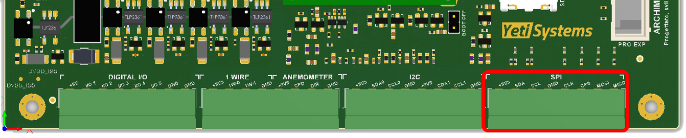
In Archimede there is one SPI interface, as any other onboard interfaces these interfaces can be powered on and off using GPIO.
| Interface | Enable PIN | RoadRunner PIN |
|---|---|---|
| 3V3 - Supply ON | PA13 | - |
| SPI0 - SPCK | - | PA14 |
| SPI0 - MOSI | - | PA15 |
| SPI0 - MISO | - | PA16 |
| SPI0 - CPG == NCPS (Chip Select Active Low) | - | PA17 |
| i2c - SDA2 | - | PC6 |
| i2c - SCL2 | - | PC7 |
For info about how to power on and off the interface see —LINK A UNA PAGINA DEDICATA—
Use SPI from userspace
The default DTS defines a generic spidev device attached to the SPI port and this can be used from userspace using the device file /dev/spidev32766.0
For more information about the spidev can be found in the Linux Kernel documentation
It is possible to test the interface directly using linux shell (for example attaching an oscilloscope to the interface), for example:
# Write binary 1, 2 and 3
$ echo -ne "\x01\x02\x03" > /dev/spidev32766.0
In order to use specif driver you need to modify the dts and recompile the dtb setting the specific device type.
Example 1: Loopback test
This can be used to test SPI send and receive. Put a wire between MOSI and MISO.
$ wget https://raw.githubusercontent.com/raspberrypi/linux/rpi-3.10.y/Documentation/spi/spidev_test.c
$ gcc -o spidev_test spidev_test.c
$ ./spidev_test -D /dev/spidev32766.0
spi mode: 0
bits per word: 8
max speed: 500000 Hz (500 KHz)

FF FF FF FF FF FF
40 00 00 00 00 95
FF FF FF FF FF FF
FF FF FF FF FF FF
FF FF FF FF FF FF
DE AD BE EF BA AD
F0 0D
Contact US
For clarification or suggestions to improve the documentation